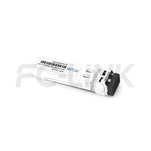
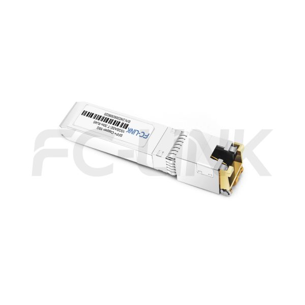
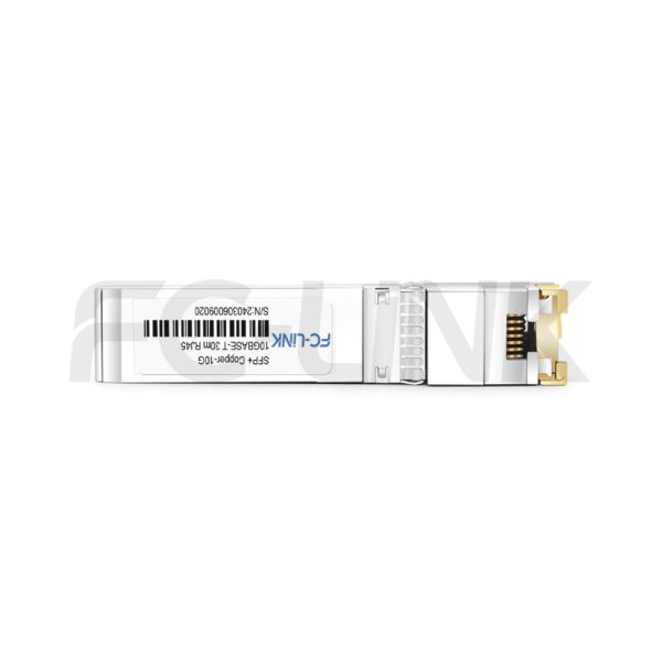
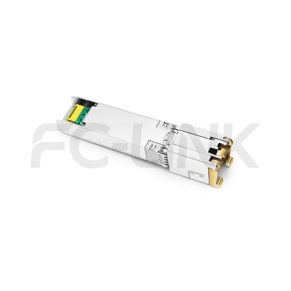
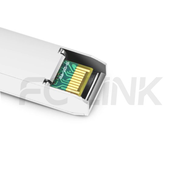
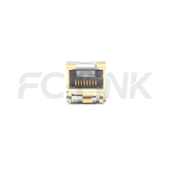
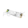
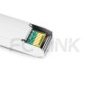
Generic Compatible 10GBASE-T SFP+ 30m Copper RJ45 Transceiver Module

SFP+CO-10A-003-RJ45

Category: Tags: , , , Brand:
  • Broad Multi-Brand Compatibility
  • Flexible Customization Support
  • Tested for Reliable Performance
  • Fast Response & Delivery
  • Professional Technical Support

The FC-LINK SFP+ Copper 10GBASE-T RJ45 transceiver Small Form Pluggable (SFP ) modules, with a reach of 30 meters, adhere to the SFP Multi Source Agreement (MSA). They are fully compliant with the 10GBASE-T, 1000BASE-T, and 100BASE-TX standards outlined in IEEE 802.3an, 802.3ab, and 802.3au.

SPECIFICATIONS
Product ModelSFP+CO-10A-003-RJ45Manufacturer brandFC-LINK
Package TypeSFP+Interface TypeRJ45
Max Data Rate10.3Gbps10G Effective transmission distance(OM4)30m
Hot-Pluggable SFPYESOperating voltage3.3V
Power Consumption1.5WProtocolsSFP MSA
SFF-8472
Operating temperature(Extended)-10℃~+70℃Storage Temperature(Commercial)-40℃~+85℃
Operating Temperature(Industrial)-40℃~+85℃Storage Temperature(Industrial)-40℃~+85℃
Data center optical transceiver application scenario
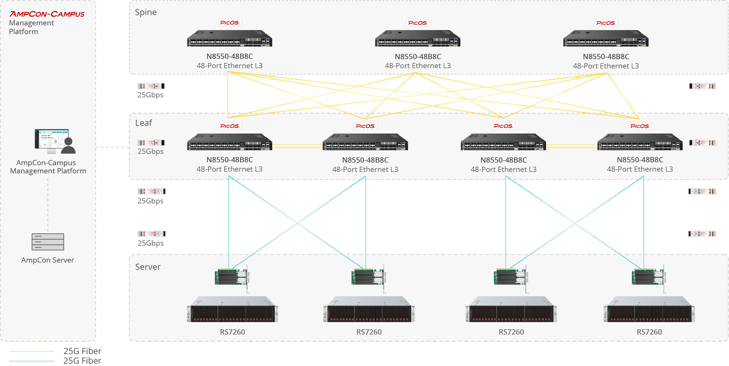
Server-to-Switch Data Center Links

Used for 10G/25G/100G optical uplinks between servers and top-of-rack switches in high-density data center deployments.

Enterprise network fiber optic application scenario
Building-to-Building Campus Backbone

Suitable for 1G/10G fiber links between office buildings, campus distribution rooms, and backbone aggregation points.

Telecom fiber optic link application scenario
Access-to-Core Enterprise Uplinks

Designed for switch uplinks from access to aggregation or core layers in enterprise and campus network architectures.

Industrial fiber optic network application scenario
Industrial Switching in Harsh Environments

Applied in industrial Ethernet, automation systems, and outdoor cabinets where wider temperature tolerance and stable fiber communication are required.


1
1
1

Compatible Brands

Customization Options

Vendor Coding
Private Label
Custom Part Number
Packaging Design
Temperature Grade Selection
Absolute Maximum Ratings
ParameterSymbolMin.Typ.Max.Units
Maximum supply voltageVcc-0.5-4.0V
Storage temperatureTS-40-85°C
Normal Operating Condition
ParameterSymbolMinTyp.MaxUnits
Operating case temperatureTcSFP+CO-10A-003-RJ45-10-70°C
Supply voltageVcc3.153.33.45V
Electrical Characteristics
ParameterSymbolMinTyp.MaxUnitsNotes/Conditions
+3.3 Volt Electrical Power Interface
Supply currentIcc
--710mASFP+CO-10A-003-RJ45
Input voltageVcc3.153.33.45V-
Low-Speed Signals, Electronic Characteristics
SFP output lowVOL0-0.5V4.7k to 10k pull-up to host_Vcc, measured at host side of connector
SFP output highVOHVcc–0.5-Vcc+0.3-4.7k to 10k pull-up to host_Vcc, measured at host side of connector
SFP input lowVIL0-0.4-4.7k to 10k pull-up to Vcc, measured at SFP side of connector
SFP input highVIH2.8-Vcc+0.3-4.7k to 10k pull-up to Vcc, measured at SFP side of connector
High-Speed Electrical Interface, Transmission Line-SFP
Tx output impedanceZout,TX-100-Ohm-
Rx input impedanceZin,RX-100-Ohm-
High-Speed Electrical Interface, Host-SFP
CML Inputs(Differential)Vin250-1200mVAC coupled inputs
CML outputs(Differential)Vout350-800mVCML outputs(Differential)
Rise/Fall timeTr,Tf-20-psec20%-80%
Tx input impedanceZin-100-OhmDifferential ended
Rx output impedanceZout-100-OhmDifferential ended
Pin Descriptions
Pin No.NameFunctionPlug Seq.Notes
1VeeTTransmitter ground1-
2TX FaultTransmitter fault indication3Not used
3TX DisableTransmitter disable3Note1
4MOD-DEF2Module definition 23Note2
5MOD-DEF1Module definition 13Note2
6MOD-DEF0Module definition 03Note2
7RS0No connection required3-
8LOSLoss of signal3RX_LOSS
9RS1No connection required1-
10VeeRReceiver ground1-
11VeeRReceiver ground1-
12RD-Inv. Received data out3-
13RD+Received data out3-
14VeeRReceiver ground1-
15VccRReceiver power2-
16VccTTransmitter power2-
17VeeTTransmitter ground1-
18TD+Transmit data in3-
19TD-Inv. Transmit data in3-
20VeeTTransmitter ground1-
Notes:
Note1: TX disable is an input that is used to shut down the transmitter optical output. It is pulled up within the module with a 4.7–10KΩ resistor. Its states are:
Low (0–0.8V): Transmitter on
(>0.8, < 2.0V): Undefined
High (2.0 – 3.465V): Transmitter Disabled

Note2: Mod-Def 0,1,2. These are the module definition pins. They should be pulled up with a 4.7K–10KΩ
resistor on the host board. The pull-up voltage shall be VccT or VccR.
Mod-Def 0 is grounded by the module to indicate that the module is present.
Mod-Def 1 is the clock line of two wire serial interface for serial ID.
Mod-Def 2 is the data line of two wire serial interface for serial ID.

The following is the Diagram of host board connector block pin numbers and names

Generic Compatible 10GBASE-T SFP+ 30m Copper RJ45 Transceiver Module
SERIAL COMMUNICATION PROTOCOL

FC-LINK Copper SFP support the 2-wire serial communication protocol defined in the SFP MSA.These SFP use a 128 byte EEPROM with an address of A0H.

Eeprom Serial ID Memory Contents
Accessing Serial ID Memory uses the 2 wire address 1010000X (A0H). Memory Contents of Serial ID are shown in Table 1.
Table 1 Serial ID Memory Contents
Data AddrField Size(Byte)Name of FiledDescription of FieldCoded ValueHex
BASE ID FIELDS
01IdentifierTypeof serial transceiverSFP+3
11Ext.IdentifierExtended identifier of type of serial transceiverMOD_DEF 44
21ConnectorCode for connector typeRJ4522
38Transceiver10G Ethernet compliance codes & infiniband compliance codes-0
4Part of SONET compliance codes-0
5SONET compliance codes-0
6Ethernet compliance codes-0
7Fiber channel link length & part of Fibre channel technology-0
8Part of fiber channel transmitter technology-0
9Fiber channel transmission media-0
10Fiber channel speed-0
111EncodingCode for high speed serial encoding algorithm64B/66B6
121BR, NominalNominal signalling rate, units of 100MBd.10.3Gbps67
131Rate IdentifierTypeof rate select functionality-0
141Length(SMF,km)Link length supported for single mode fiber, units of km-0
151Length (SMF)Link length supported for single mode fiber, units of 100 m-0
161Length (50um)Link length supported for 50um OM2 fiber, units of 10 m-0
171Length (62.5um)Link length supported for 62.5um OM1 fiber, units of 10 m-0
181Length (Copper)Link length supported for copper, units of meters30m1E
191Length (OM3)Link length supported for 50um OM3 fiber, units of 10 m-0
2016Vendor nameVendor name (ASCII)E45
21o6F
22p70
23t74
24o6F
25l6C
26i69
27n6E
28k6B
29<space>20
30<space>20
31<space>20
32<space>20
33<space>20
34<space>20
35<space>20
361TransceiverExtended compliance codes10GBASE-T Short Reach (30 meters)1C
373Vendor OUISF P vendor IEEE company ID-0
38-0
39-0
4016Vendor PNPart number provided by vendor (ASCII)E45
41O4F
42L4C
43T54
44-2D
45C43
46939
47636
48-2D
49030
50232
51<space>/-20/2D
52<space>/I20/49
53<space>20
54<space>20
55<space>20
564Vendor revRevision level for part number provided by vendor (ASCII)131
57-2E
58030
59<space>20
602WavelengthLaser wavelength-0
610
621Reserved0
631CC_BASECheck code for base ID fields (addresses 0 to 62)Note3xx
642OptionsIndicates which optional transceiver signals are implementedTX_DISABLEsignal,Rx_LOS0
6512
661BR, maxUpper bitrate margin, units of %-0
671BR, minLower bitrate margin, units of %-0
6816Vendor SNSerial number provided by vendor(ASCII)xxx
69xxx
70xxx
71xxx
72xxx
73xxx
74xxx
75xxx
76xxx
77xxx
78<space>20
79<space>20
80<space>20
81<space>20
82<space>20
83<space>20
848Date codeVendor’s manufacturing date codeYearxx
85Yearxx
86Monthxx
87Monthxx
88Dayxx
89Dayxx
90<Space>20
91<Space>20
921Diagnostic monitoring typeTypeof diagnostic monitoring is implementeddiagnostic monitoring is not implemented0
931Enhanced optionsOptional enhanced features are implementedOptional enhanced
features are not
implemented
0
941SFF-8472 ComplianceRevision of SFF-8472 the transceiver complies withDigital diagnostic functionality not included or undefined0
951CC_EXTCheck code for the extended ID fields (addresses 64 to 94)Note4xx
Note3. The check code shall be the low order 8 bits of the sum of the contents of all the bytes from byte 0 to byte 62, inclusive.
Note4. The check code shall be the low order 8 bits of the sum of the contents of all the bytes from byte 64 to byte 94, inclusive.
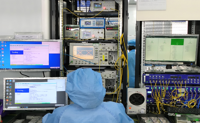
Optical transceiver TX RX performance test
Performance Testing

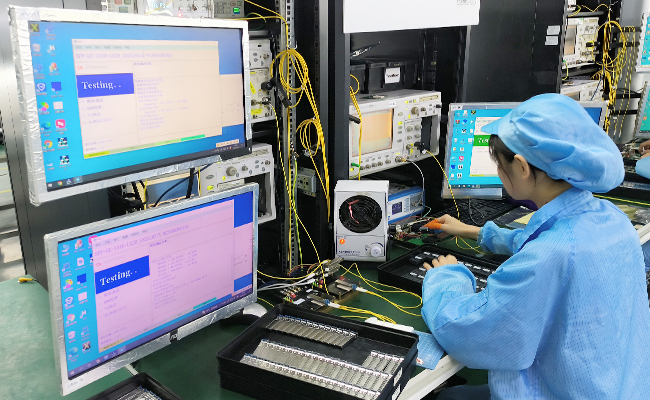
Each module is tested before shipment to help ensure stable optical and electrical performance.
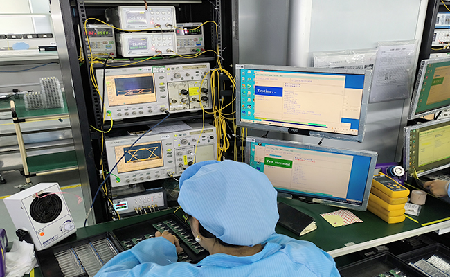
Optical transceiver compatibility test
Compatibility Verification

Compatibility validation is available for major switch and router platforms.
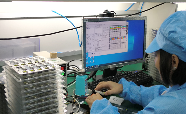
Optical transceiver aging and reliability test
Reliability Screening

Selected products support aging, temperature cycle, and stability testing for demanding applications.
Automatic labeling and traceability for optical transceivers
Traceable Quality Control

Inspection and production records support more consistent quality control and batch traceability.

光模块产品详情订购信息---QSFP+