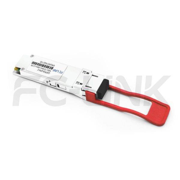
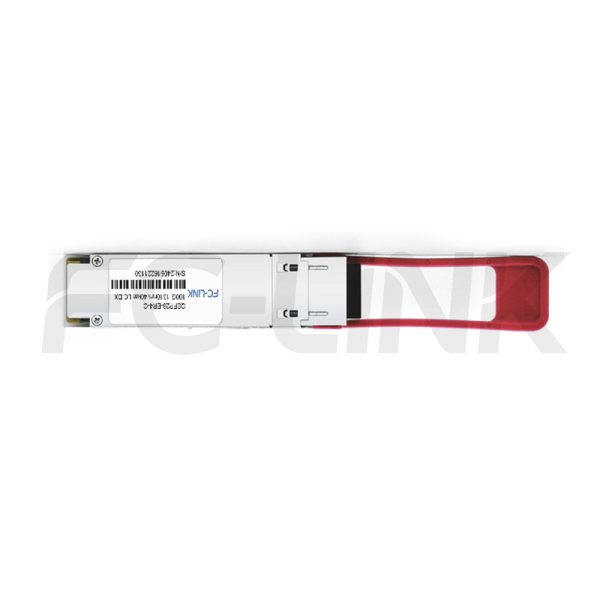
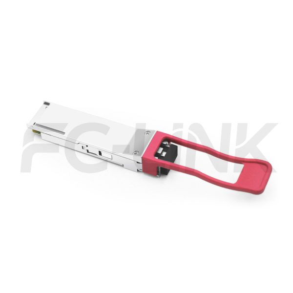
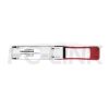

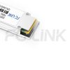
Generic Compatible 100GBASE-LR4 QSFP28 40km Breakout DOM Duplex LC SMF Optical Transceiver Module

QSFP28-103/112-LW-40(ER4)-LCD

Category: Tags: , , , , , Brand:
  • Broad Multi-Brand Compatibility
  • Flexible Customization Support
  • Tested for Reliable Performance
  • Fast Response & Delivery
  • Professional Technical Support

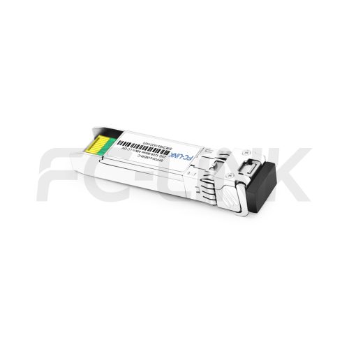
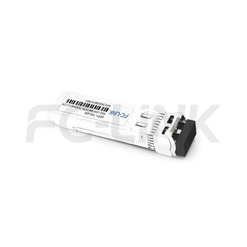
The FC-LINK QSFP28 100G LAN-WDM 40km ER4 LC DX is a high-performance 100Gb/s transceiver module designed for optical communication applications compliant with the Ethernet 100GBASE-ER4 standard. It converts four 25Gb/s electrical input channels into four LAN WDM optical signals, multiplexing them into a single channel for 100Gb/s optical transmission. On the receiver side, it de-multiplexes the 100Gb/s optical input back into four LAN WDM optical signals and converts them into four electrical output channels.The central wavelengths of the four LAN WDM channels are 1295.56nm, 1300.05nm, 1304.58nm, and 1309.14nm, consistent with the LAN WDM wavelength grid defined in IEEE 802.3ba. Equipped with high-performance cooled LAN WDM DFB transmitters and high-sensitivity APD receivers, the module ensures exceptional performance for 100Gigabit Ethernet applications over links up to 40km.Designed according to the QSFP+ Multi-Source Agreement (MSA), the transceiver features a compact form factor, reliable optical/electrical connections, and a digital diagnostic interface. Built to withstand extreme operating conditions, including high temperatures, humidity, and EMI interference, it ensures robust and reliable performance in demanding environments.

SPECIFICATIONS
Product ModelQSFP28-103/112-LW-40(ER4)-LCDManufacturer brandFC-LINK
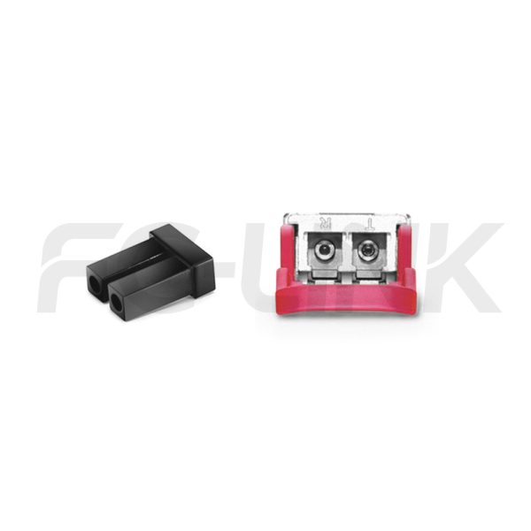
Package TypeQSFP28Optical connectorLC DX
Max Data Rate103.1GbpsChannel Data Rate25.78125Gbps
Effective transmission distance40km
Wavelength1310nmOperating voltage3.3V
Fiber TypeSMFCore Size9/125
Transmitter TypeDFBReceiver TypePIN
TX Power-2.9~4.5dBmReceiver Sensitivity-18.6dBm
Digital Optical Monitoring(DOM)YESReceiver Overload-4.9dBm
Power Consumption<4.5WProtocols100GBASE-ER4 Ethernet Links
Infiniband QDR and DDR interconnects
Operating temperature(Commercial)0℃~+70℃Storage Temperature(Commercial)-40℃~+85℃
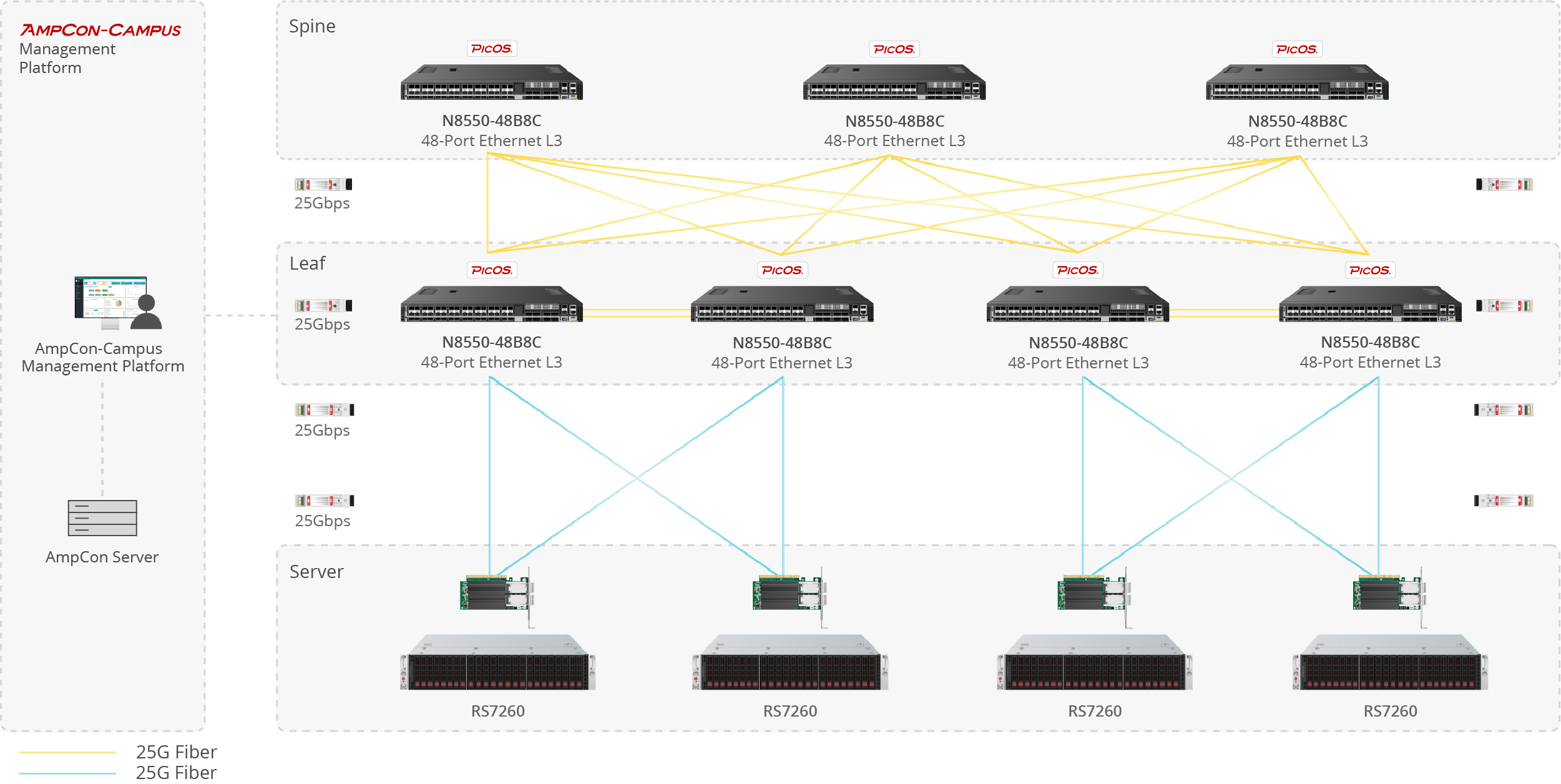
Data center optical transceiver application scenario
Server-to-Switch Data Center Links

Used for 10G/25G/100G optical uplinks between servers and top-of-rack switches in high-density data center deployments.

Enterprise network fiber optic application scenario
Building-to-Building Campus Backbone

Suitable for 1G/10G fiber links between office buildings, campus distribution rooms, and backbone aggregation points.

Telecom fiber optic link application scenario
Access-to-Core Enterprise Uplinks

Designed for switch uplinks from access to aggregation or core layers in enterprise and campus network architectures.

Industrial fiber optic network application scenario
Industrial Switching in Harsh Environments

Applied in industrial Ethernet, automation systems, and outdoor cabinets where wider temperature tolerance and stable fiber communication are required.


1
1
1

Compatible Brands

Customization Options

Vendor Coding
Private Label
Custom Part Number
Packaging Design
Temperature Grade Selection
Absolute Maximum Ratings
ParameterSymbolMin.Max.Unit
Supply voltageVCC-0.53.6V
Storage temperatureTC-2085
Relative humidityRH585%
These values represent the damage threshold of the module.Stress in excess of any of theindividual absolute maximum ratings can cause immediate catastrophic damage to the module even if all other parameters are within recommended operating conditions.
Recommended Operating Environment
ParameterSymbolMinTypicalMaxUnit
Power supply voltageVCC3.133.33.47V
Operating case temperatureTca0-70
Data rate per lanefd-25.78125-Gb/s
Link distanceD--40km
Electrical Characteristics
ParameterSymbolMinTypicalMaxUnitRef
Transmitter Section:
Input differential impedanceRin90100110Ω1
Differential input voltage amplitudeVin900--mVp-p2
Receiver
Output differential impedanceRout90100110Ω1
Differential output voltage
amplitude
Vout--900mVp-p3
Notes:
[1]AC coupled.
[2]Differential input voltage amplitude is measuredbetween TxnP and TxnN.
[3]Differentialoutput voltage amplitude is measured between RxnP and RxnN.
TransmitterSpecifications-Optical
ParameterSymbolMinTypicalMaxUnit
Center wavelengthCh0λ01294.531295.561296.59nm
Ch1λ11299.021300.051301.09nm
Ch2λ21303.541304.581305.63nm
Ch3λ31308.091309.141310.09nm
Bit rate per channelBR25.78125±100ppmGb/s
Side mode suppression ratioSMSR30--dB
Average launch power,each lane--2.9-4.5dBm
Launch power in OMA minus TDP,each laneOMA-TDP-0.65--dBm
Transmission & dispersion penalty, each laneTDP--2.5dB
Relative intensity noiseRIN---130dB/Hz
Transmitter reflectanceRT---12dB
Extinction ratioER7--dB
Transmitter eyemask definition
{X1,X2,X3,Y1,Y2,Y3}
{0.25,0.4,0.45,0.25,0.28,0.4}
Average launch power of OFF transmitter,each lane----30dBm
Optical return loss tolerance---20dB
Receiver Specifications-Optical
ParameterSymbolMin.TypicalMax.Unit
Center wavelengthCh0λ01294.531295.561296.59nm
Ch1λ11299.021300.051301.09nm
Ch2λ21303.541304.581305.63nm
Ch3λ31308.091309.141310.09nm
Bit rate per channelBR25.78125±100ppmGb/s
Damage threshold,each lane----3dBm
Averagereceive power,each lane--20.9--4.9dbm
Unstressed sensitivity(OMA) at 5×10⁵BEROMA---18.6dBm
LOS assertLOSA-30--dBm
LOS de-assertLOSD---24dBm
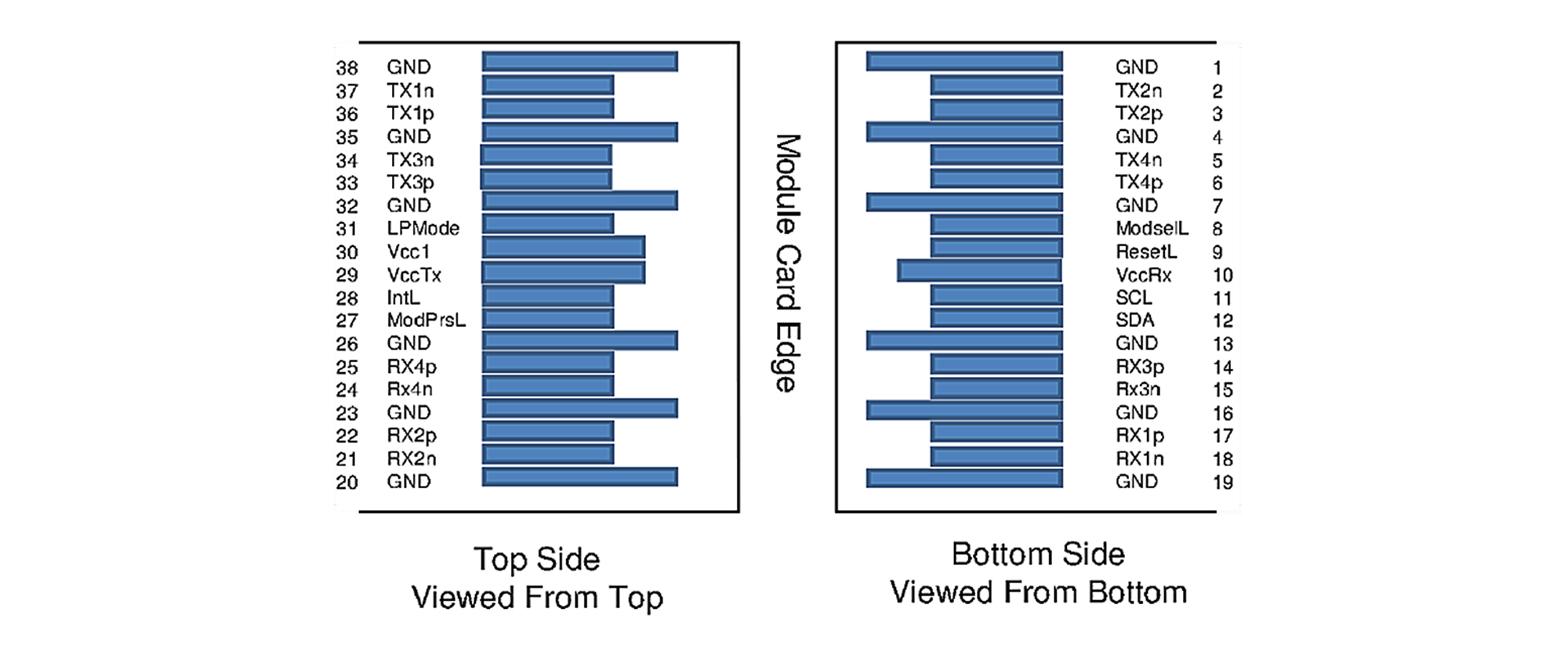
Pin Descriptions

Generic Compatible 100GBASE-LR4 QSFP28 40km Breakout DOM Duplex LC SMF Optical Transceiver Module
Pin Definition
PinSymbolName/Description
1GNDGround
2Tx2nTransmitter inverted data input
3Tx2pTransmitter non-inverted data input
4GNDGround
5Tx4nTransmitter inverted data input
6Tx4pTransmitter non-inverted data input
7GNDGround
8ModSelLModule select
9ResetLModule reset
10VCCRx+3.3V power supply receiver
11SCL2-wire serial interface clock
12SDA2-wire serial interface data
13GNDGround
14Rx3pReceiver non-inverted data output
15Rx3nReceiver inverted data output
16GNDGround
17RxlpReceiver non-inverted data output
18Rx1nReceiver inverted data output
19GNDGround
20GNDGround
21Rx2nReceiver inverted data output
22Rx2pReceiver non-inverted data output
23GNDGround
24Rx4nReceiver inverted data output
25Rx4pReceiver non-inverted data output
26GNDGround
27ModPrsLModule present
28IntLInterrupt
29VCCTx+3.3V power supply transmitter
30VCC1+3.3V power supply
31LPModeLow power mode
32GNDGround
33Tx3pTransmitter non-inverted data input
34Tx3nTransmitter inverted data input
35GNDGround
36TxlpTransmitter non-inverted data input
37Tx1nTransmitter inverted data input
38GNDGround
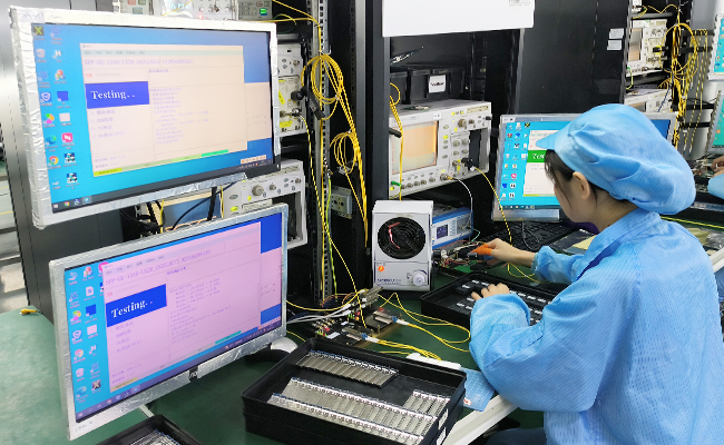
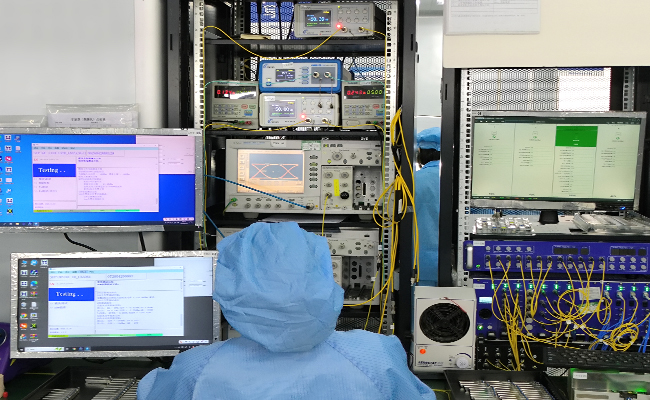
Optical transceiver TX RX performance test
Performance Testing

Each module is tested before shipment to help ensure stable optical and electrical performance.
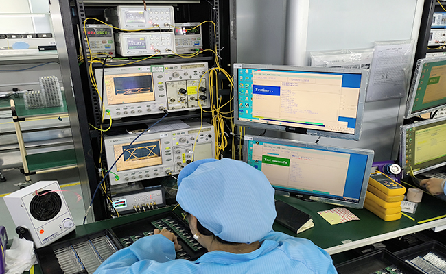
Optical transceiver compatibility test
Compatibility Verification

Compatibility validation is available for major switch and router platforms.
Optical transceiver aging and reliability test
Reliability Screening

Selected products support aging, temperature cycle, and stability testing for demanding applications.
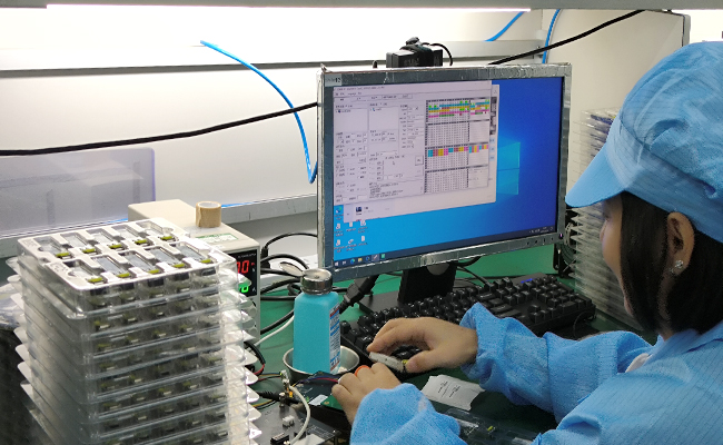
Automatic labeling and traceability for optical transceivers
Traceable Quality Control

Inspection and production records support more consistent quality control and batch traceability.

光模块产品详情订购信息---QSFP+