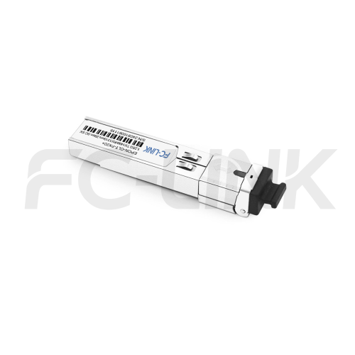
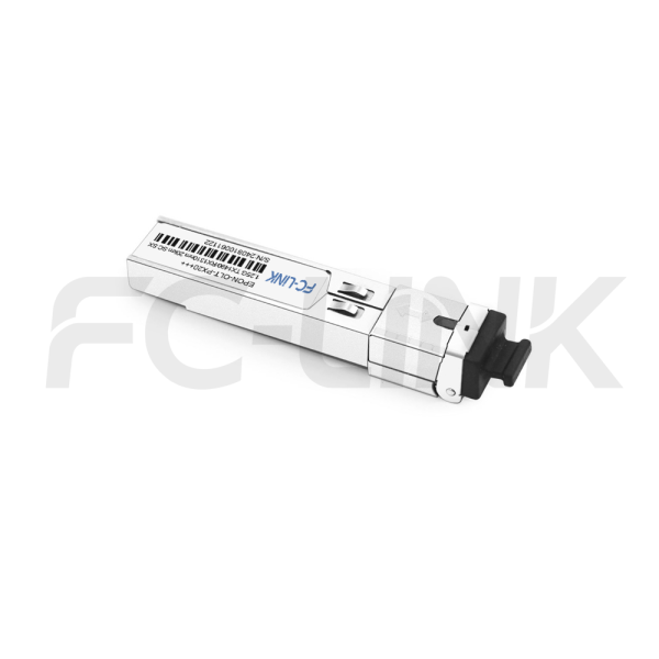
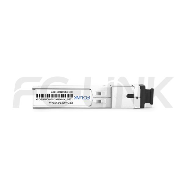
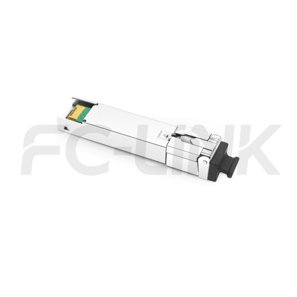
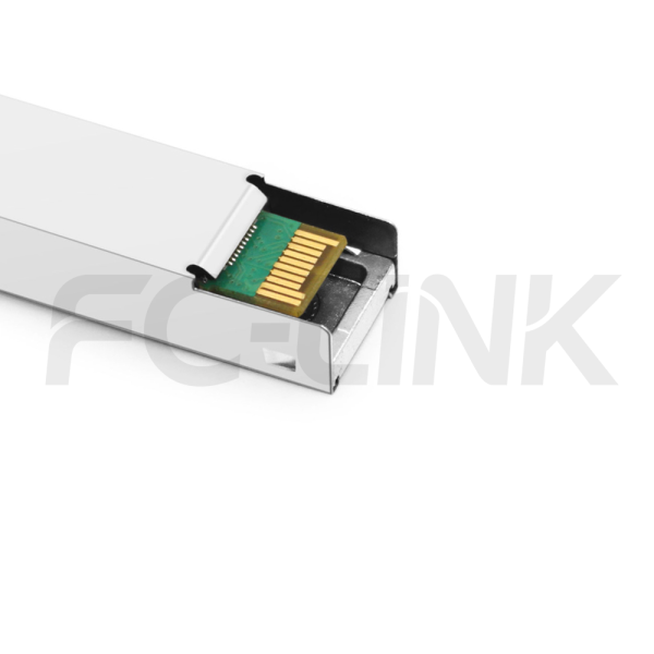
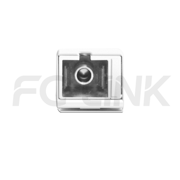
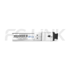
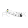
1.25G SFP PX20+++ EPON OLT Transceiver for 20km SMF Links, 1490/1310nm Simplex SC

SFP-EPON-PX20+++1.25-1413-20-SCS

  • Broad Multi-Brand Compatibility
  • Flexible Customization Support
  • Tested for Reliable Performance
  • Fast Response & Delivery
  • Professional Technical Support

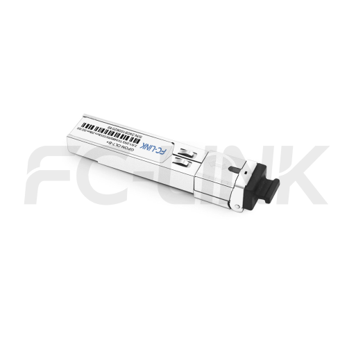
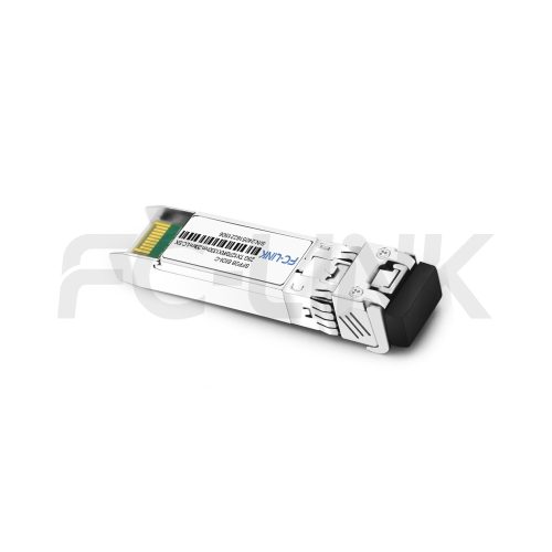
The FC-LINK EPON OLT PX20+++ 7dBm Transceiver is a high-performance 1.25G SFP module designed for Optical Line Terminal (OLT) applications, supporting 1490nm downstream transmission and 1310nm upstream reception over single-mode fiber (SMF) with a 20km reach. Featuring an SC connector interface and compliant with the premium PX20+++ class delivering a 7dBm optical budget, it incorporates 100 Ohm differential impedance for both transmitter inputs and receiver outputs. The module employs internal AC coupling on data lines, provides differential termination, and minimizes differential-to-common mode conversion to ensure superior signal integrity, robust termination quality, and reduced electromagnetic interference (EMI).

SPECIFICATIONS
Product ModelSFP-EPON-PX20+++1.25-1413-20-SCSManufacturer brandFC-LINK
Package TypeSFPOptical connectorSC
Max Data Rate1.25GbpsClassPX20+++
Effective transmission distance20KM
Wavelength1310nm/1490nm
1490nm/1310nm
Operating voltage3.3V
Fiber TypeSMFCore Size9/125µm
Transmitter TypeDFBReceiver TypeAPD
TX Power7~9dBmReceiver Sensitivity-32dBm
Digital Diagnostic Monitoring(DDM)YESReceiver Overload-8dBm
Power Consumption<1WProtocolsSFP MSA SFF-8472
Operating temperature(Commercial)0℃~+70℃Storage Temperature(Commercial)-40℃~+85℃
Operating temperature(Industrial)-40℃~+85℃Storage Temperature(Industrial)-40℃~+85℃
Data center optical transceiver application scenario
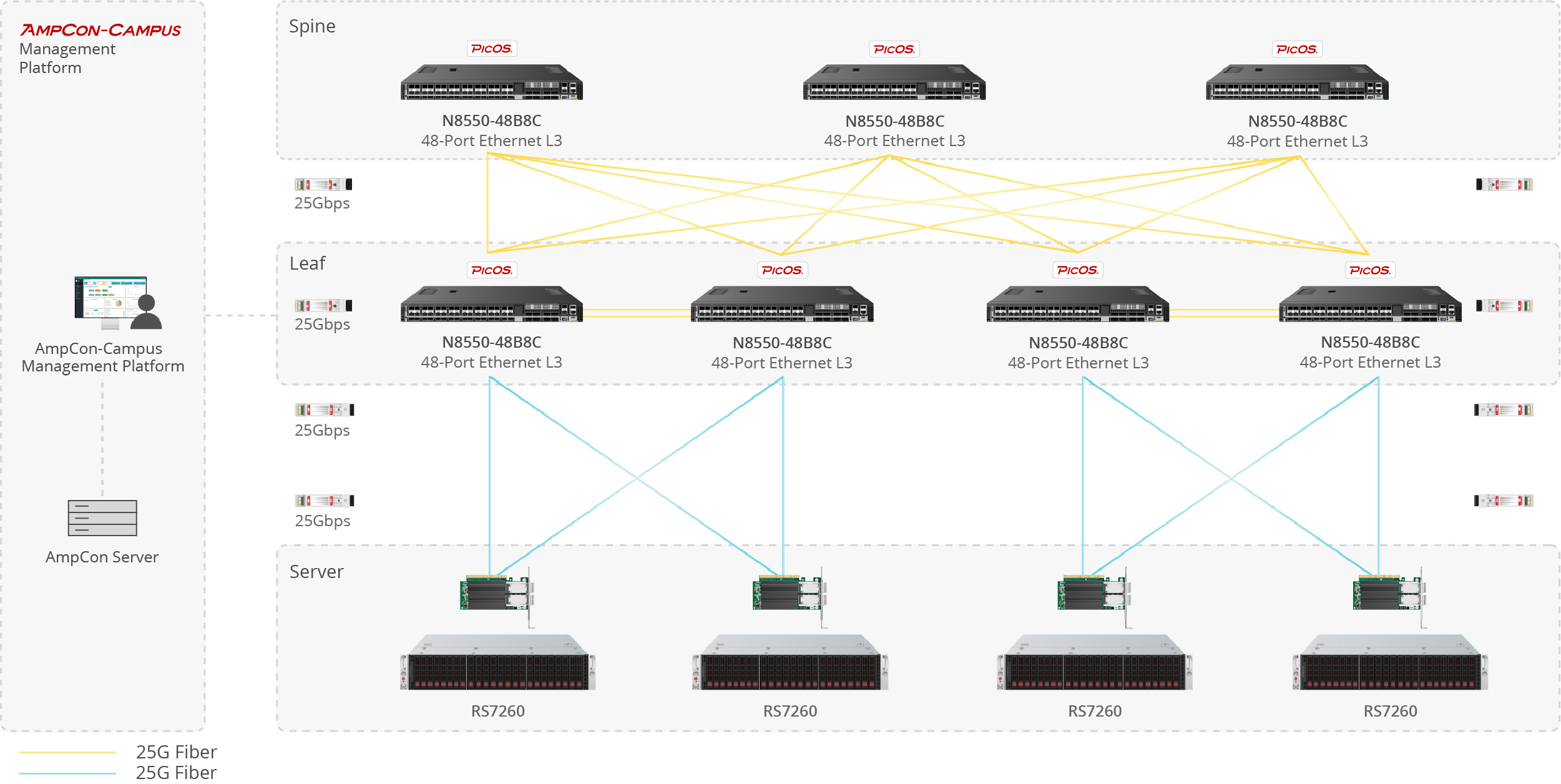
Server-to-Switch Data Center Links

Used for 10G/25G/100G optical uplinks between servers and top-of-rack switches in high-density data center deployments.

Enterprise network fiber optic application scenario
Building-to-Building Campus Backbone

Suitable for 1G/10G fiber links between office buildings, campus distribution rooms, and backbone aggregation points.

Telecom fiber optic link application scenario
Access-to-Core Enterprise Uplinks

Designed for switch uplinks from access to aggregation or core layers in enterprise and campus network architectures.

Industrial fiber optic network application scenario
Industrial Switching in Harsh Environments

Applied in industrial Ethernet, automation systems, and outdoor cabinets where wider temperature tolerance and stable fiber communication are required.


1
1
1

Compatible Brands

Customization Options

Vendor Coding
Private Label
Custom Part Number
Packaging Design
Temperature Grade Selection
Absolute Maximum Ratings
ParameterSymbolMin.Max.Unit
Power Supply VoltageVCC03.6V
Storage TemperatureTc-4085
Operating Case TemperatureTc070
TI-4085
Relative HumidityRH595%
RX Input Average PowerPmax--7dBm
These values represent the damage threshold of the module. Stress in excess of any of the individual Absolute maximum ratings can cause immediate catastrophic damage to the module even if all other parameters are within recommended operating conditions.
Recommended Operating Environment
ParameterSymbolMin.TypicalMax.Unit
Power Supply VoltageVCC3.1353.33.465V
Power Supply CurrentIcc--350mA
Operating Case
Temperature
TC02570
TI-402585
Recommended operating environment specifies parameters for which the electrical and optical characteristics hold unless otherwise noted.
Optical Characteristics
ParametersUnitValues
Operating Reachm2 - 20K
Transmitter
Center Wavelengthnm1490
Side Mode Suppression Ratio (min)dB30
Launched power
– maximum (Average)dBm9
– minimum (Average)dBm7
Average Launch Power of OFF Transmitter (max)dBm-30
Extinction Ratio (min)dB9
Optical Return Loss Tolerance (min)dB12
Receiver
Center Wavelength (range)nm1310
Receive Overload (max) in Average Power(note 1)dBm-8
Receive Sensitivity (min) in A Power(note 1)dBm-30
Receiver Reflectance (max)dB-12
Los Assert(min)dBm-33
Los Dessert(max)dBm-30
Los Hysteresis(min)dB0.5
Receiver power (damage, Max)dBm-7
Notes:
1. Average optical power shall be measured using the methods specified in TIA/EIA-455-95.
2. Power budget is defined as the different between the Rx sensitivity andthe Tx output power of the interface.
Electrical Characteristics
ParameterSymbolMin.TypicalMaxUnitNotes
Data Rate--1.25-Gbps-
Power Consumption--8001000mW-
Transmitter
Single Ended Output Voltage Tolerance--0.3-4V-
Common Mode Voltage Tolerance-15--mV-
Tx Input Diff VoltageVI180-1200mV-
Tx FaultVoL-0.3-0.4VAt 0.7mA
Data Dependent Input JitterDDJ--0.1UI-
Data Input Total JitterTJ--0.28UI-
Receiver
Single Ended Output Voltage Tolerance--0.3-4V-
Rx Output Diff Voltage Vo4002400mVLOS Assert Time LOS De‐assert Time
LOS Assert TimeTAssert500ns
LOS De‐assert TimeTDeassert500ns
Receiver Threshold Settling TimeTSETTLING250ns
Ditital Diagnostic Functions
ParameterSymbolMin.MaxUnitNotes
Temperature Monitor Absolute ErrorDMI_Temp-33degCOver Operating Temp
Laser Power Monitor Absolute ErrorDMI_TX-33dB-
Supply Voltage Monitor Absolute ErrorDMI_VCC-0.080.08VFull Operating Range
Bias Current MonitorDMI_Ibias-0.10.1mA-
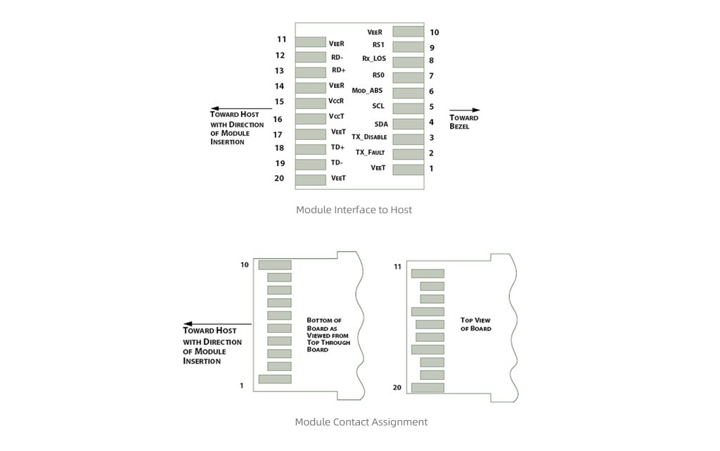
OLT SFP Module Pin Definition

OLT SFP Module Pin Definition
PINLogicSymbolName / DescriptionNote
1-VeeTModule Transmitter Ground1
2LVTTL-OTX_FaultModule Transmitter Fault-
3LVTTL-ITX_DisTransmitter Disable; Turns off Transmitter Laser Output-
4LVTTL-I/OSDA2-Wire Serial Interface Data Line2
5LVTTL-ISCL2-Wire Serial Interface Clock2
6-MOD_DEF0Module Definition, Grounded in the Module-
7LVTTL-IRS0Receiver Rate Select-
8LVTTL-ORX_LOSReceiver Loss of Signal Indication Active LOW-
9LVTTL-IRS1Transmitter Rate Select (not used)-
10-VeeRModule Receiver Ground1
11-VeeRModule Receiver Ground1
12LVPECL-ORD-Receiver Inverted Data Output-
13LVPECL-ORD+Receiver Data Output-
14-VeeRModule Receiver Ground1
15-VccRModule Receiver 3.3 V Supply-
16-VccTModule Receiver 3.3 V Supply-
17-VeeTModule Transmitter Ground1
18CML-ITD+Transmitter Non-Inverted Data Input-
19CML-ITD-Transmitter Inverted Data Input-
20-VeeTModule Transmitter Ground1
Note:
1. Module ground pins GND are isolated from the module case.
2. Shall be pulled up with 4.7K-10Kohms to a voltage between 3.15V and 3.45V on the host board.
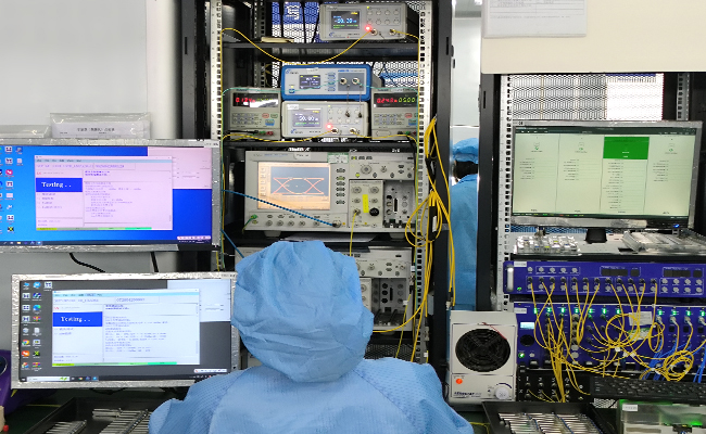
Optical transceiver TX RX performance test
Performance Testing

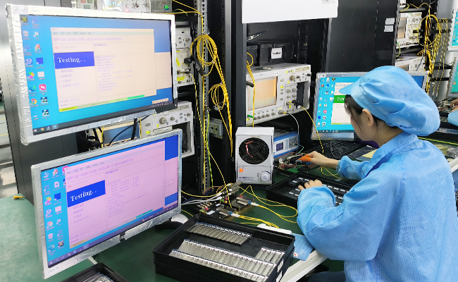
Each module is tested before shipment to help ensure stable optical and electrical performance.
Optical transceiver compatibility test
Compatibility Verification

Compatibility validation is available for major switch and router platforms.

Optical transceiver aging and reliability test
Reliability Screening

Selected products support aging, temperature cycle, and stability testing for demanding applications.
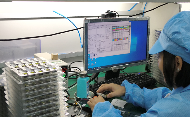
Automatic labeling and traceability for optical transceivers
Traceable Quality Control

Inspection and production records support more consistent quality control and batch traceability.

光模块产品详情订购信息---QSFP+