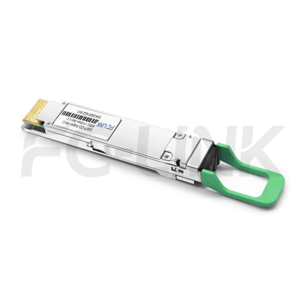
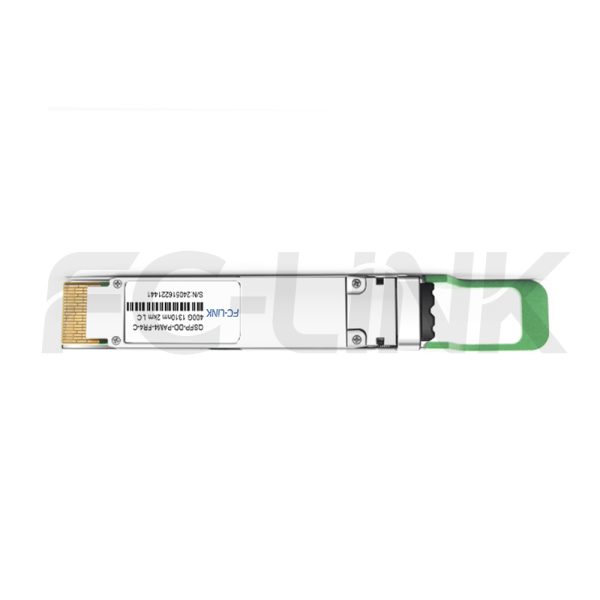
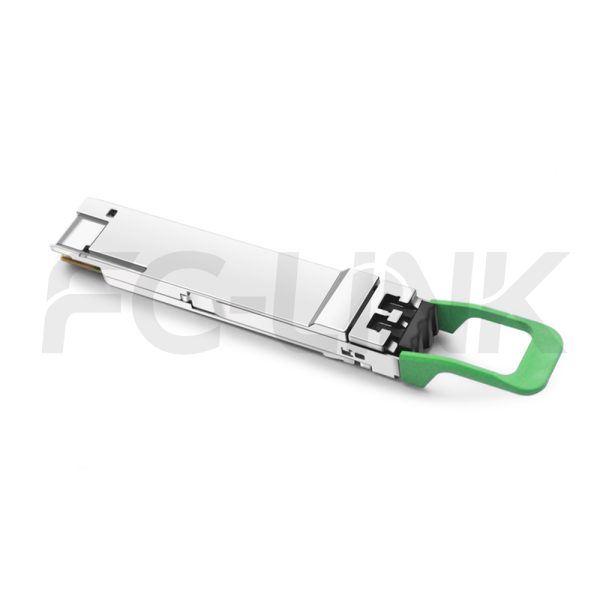
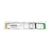

Generic Compatible 400G FR4 QSFP-DD 1310nm 2km DOM Duplex LC SMF Optical Transceiver Module

QSFPDD-400(4×100)-13-2(FR4)-LCD

Category: Tags: , , , , , Brand:
  • Broad Multi-Brand Compatibility
  • Flexible Customization Support
  • Tested for Reliable Performance
  • Fast Response & Delivery
  • Professional Technical Support

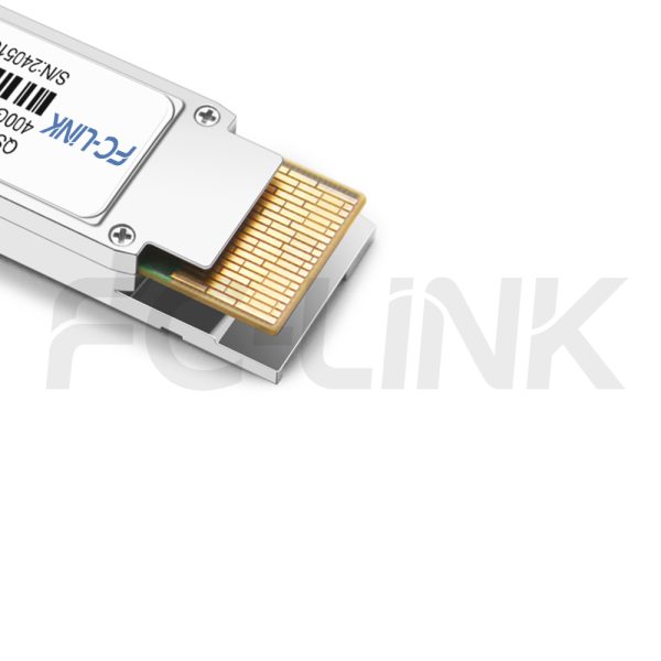
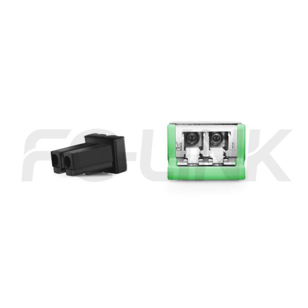
The FC-LINK QSFP-DD 400G (4x100G) 1310nm 2km FR4 LC DX transceiver is a high-performance 400Gb/s Quad Small Form Factor Pluggable-double density (QSFP-DD) optical module designed for optical communication applications over distances of up to 2km. The module converts 8 channels of 50Gb/s (PAM4) electrical input into 4 CWDM optical signals, multiplexing them into a single channel for 400Gb/s optical transmission. On the receiver side, it de-multiplexes a 400Gb/s optical input into 4 CWDM optical signals and converts them back into 8 channels of 50Gb/s (PAM4) electrical output.The 4 CWDM channels operate at central wavelengths of 1271nm, 1291nm, 1311nm, and 1331nm, as defined by the CWDM wavelength grid in ITU-T G.694.2. The transceiver features a duplex LC connector for the optical interface and a 76-pin connector for the electrical interface. To ensure minimal optical dispersion over long distances, single-mode fiber (SMF) is required for this module. Host Forward Error Correction (FEC) is also necessary to support transmission over 2km.With its advanced design and adherence to industry standards, this transceiver is an ideal solution for high-speed, long-range optical communication applications.

SPECIFICATIONS
Product ModelQSFPDD-400(4x100)-13-2(FR4)-LCDManufacturer brandFC-LINK
Package TypeQSFPDDOptical connectorLC DX
Max Data Rate400GbpsChannel Data Rate53.125Gbps
Effective transmission distance2km
Wavelength1310nmOperating voltage3.3V
Fiber TypeSMFCore Size9/125
Transmitter TypeVCSELReceiver TypePIN
TX Power-3.3~3.5dBmReceiver Sensitivity-4.6dBm
Digital Optical Monitoring(DOM)YESReceiver Overload3.5dBm
Power Consumption<10WProtocols400G Ethernet
Infiniband interconnect
Data center
Enterprise Networking
MSA
Operating temperature(Commercial)0℃~+70℃Storage Temperature(Commercial)-40℃~+85℃
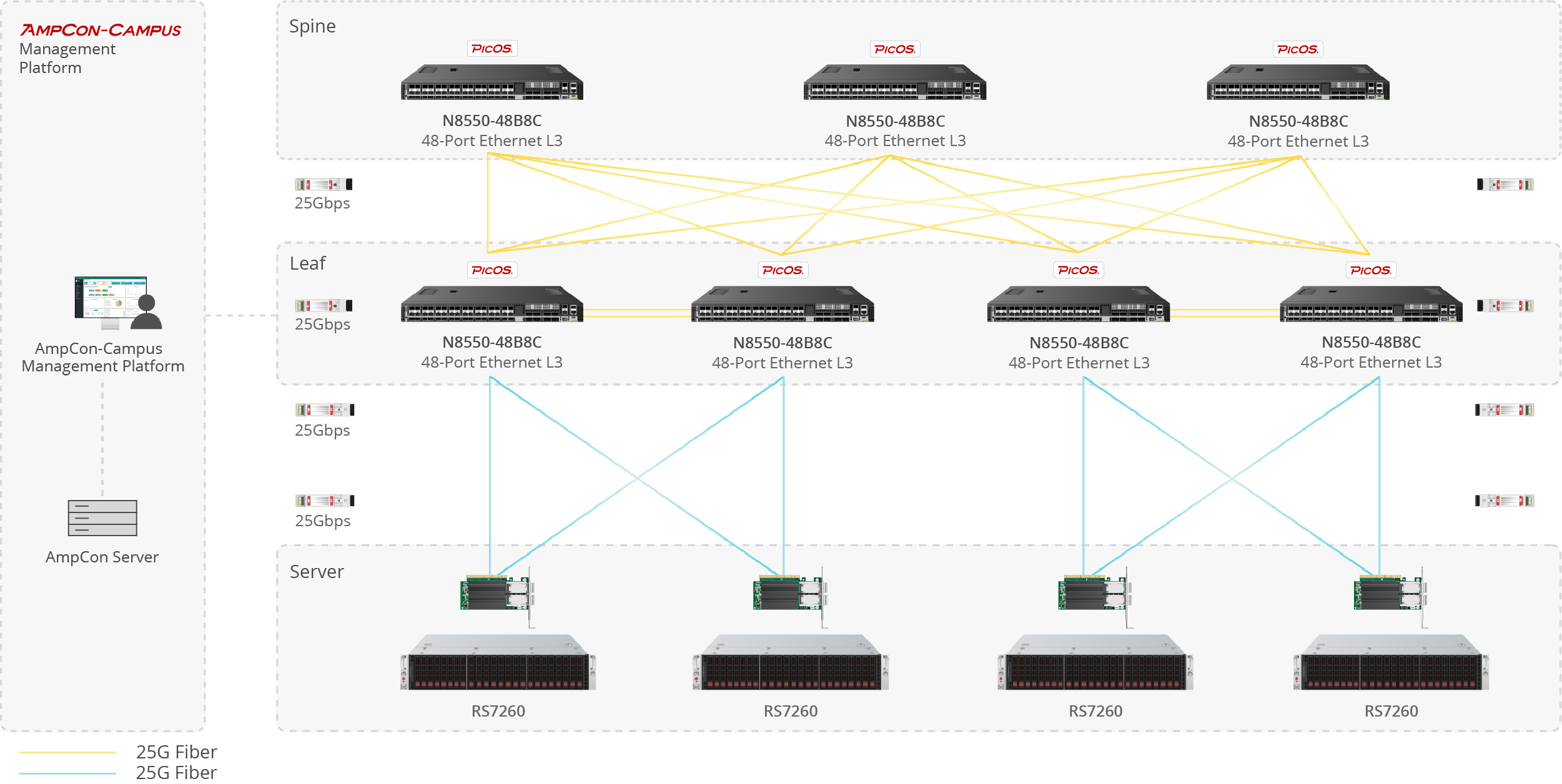
Data center optical transceiver application scenario
Server-to-Switch Data Center Links

Used for 10G/25G/100G optical uplinks between servers and top-of-rack switches in high-density data center deployments.

Enterprise network fiber optic application scenario
Building-to-Building Campus Backbone

Suitable for 1G/10G fiber links between office buildings, campus distribution rooms, and backbone aggregation points.

Telecom fiber optic link application scenario
Access-to-Core Enterprise Uplinks

Designed for switch uplinks from access to aggregation or core layers in enterprise and campus network architectures.

Industrial fiber optic network application scenario
Industrial Switching in Harsh Environments

Applied in industrial Ethernet, automation systems, and outdoor cabinets where wider temperature tolerance and stable fiber communication are required.


1
1
1

Compatible Brands

Customization Options

Vendor Coding
Private Label
Custom Part Number
Packaging Design
Temperature Grade Selection
Absolute Maximum Ratings
ParameterSymbolMin.Max.Unit
Power supply voltageVCC-0.53.6V
Storage temperatureTC-4085°C
Relative humidityRH085%
These values represent the damage threshold of the module.Stress in excess of any of theindividual absolute maximum ratings can cause immediate catastrophic damage to the module even if all other parameters are within recommended operating conditions.
Recommended Operating Environment
ParameterSymbolMin.TypicalMaxUnit
Power supply voltageVCC3.1353.33.465V
Operating case temperatureTca0-70
Recommended operating environment specifies parameters for which the electrical and optical characteristics hold unless otherwise noted.
Electrical Characteristics
ParameterSymbolMinTypicalMaxUnitNotes
Data rate per laneDR53.125±100ppmGbps-
Transmitter
Input differential impedanceRin90100110Ω-
Differential input voltage swingVin900-1100mVp-p-
Receiver
Differential output swingVout--900mVp-p-
Output differential impedanceRout900100110Ω-
The following electrical characteristics are defined over the recommended operating environment unless otherwise specified.
Optical Characteristics
ParameterSymbolMinTypicalMaxUnitNotes
Transmitter
Center wavelengthCh0λ01264.512711277.5nm-
Ch1λ11284.512911297.5
Ch2λ21304.513111317.5
Ch3λ31324.513311337.5
Data rate,each lane53.125±100ppmGBd-
Side-mode suppression ratioSMSR30--dB-
Average optical power,per lanePo-3.3-3.5dBm1
Extinction ratioER3.5--dBm-
Transmitter and dispersion eye closureTDECQ--3.4dB-
Optical return loss toleranceORL--17.1dB-
Receiver
Center wavelengthCh0λ01264.512711277.5nm-
Ch1λ11284.512911297.5
Ch2λ21304.513111317.5
Ch3λ31324.513311337.5
Data rate,each lane-53.125±100ppmGBd-
Average receive power,each lane--7.3-3.5dBm-
Receive power(OMAouter),
each lane
---3.7dBm-
Receiver sensitivity(OMAouter),
each lane
----4.6dBm2
LOS assertedLsa-20--dBm-
LOS de-assertedLda--10.3dBm-
LOS hysteresisLh0.5--dB-
Note:
[1]Average launch power,each lane(min)isinformative and not the principal indicator ofsignal strength.Atransmitter with launch power below this value cannot be compliant;however,avalue above this does not ensure compliance.
[2]Measured with conformance test signal at TP3 for BER=2.4E-4 Pre-FEC
The following optical characteristics are defined over the Recommended Operating Environment unless otherwise specified.
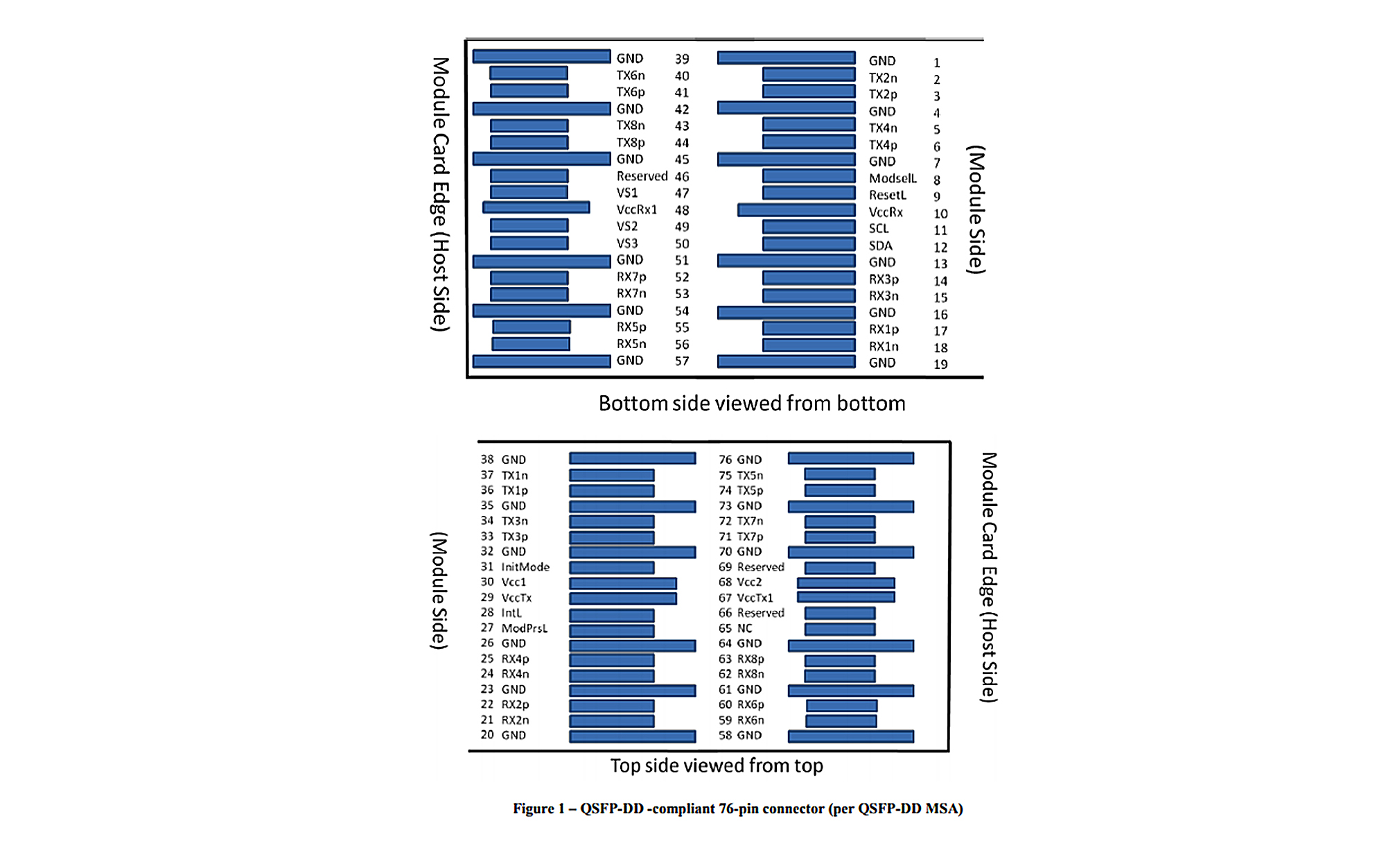
QSFP-DD Transceiver Electrical Pad Layout

Generic Compatible 400G FR4 QSFP-DD 1310nm 2km DOM Duplex LC SMF Optical Transceiver Module
Pin Definition
PadLogicSymbolName/Description
1-GNDGround
2CML-ITx2nTransmitter inverted data input
3CML-ITx2pTransmitter non-inverted data input
4-GNDGround
5CML-ITx4nTransmitter inverted data input
6CML-ITx4pTransmitter non-inverted data input
7-GNDGround
8LVTTL-IModSelLModule select
9LVTTL-IResetLModule reset
10-Vcc Rx+3.3V Power supply receiver
11LVCMOS- I/OSCL2-wire serial interface clock
12LVCMOS- I/OSDA2-wireserial interface data
13-GNDGround
14CML-ORx3pReceiver non-inverted data output
15CML-ORx3nReceiver inverted data output
16-GNDGround
17CML-ORx1pReceiver non-inverted data output
18CML-ORx1nReceiver inverted data output
19-GNDGround
20-GNDGround
21CML-ORx2nReceiver onverted data output
22CML-ORx2pReceiver non-inverted data output
23-GNDGround
24CML-ORx4nReceiver inverted data output
25CML-ORx4pReceiver non-onverted data output
26-GNDGround
27LVTTL-OModPrsLModule present
28LVTTL-OIntLInterrupt
29-VCC Tx+3.3V power supply transmitter
30-VCC1+3.3V power supply
31LVTTL-IInitModeInitialization mode;in legacy QSFP applications,the initMode pad is called LPMODE
32-GNDGround
33CML-ITx3pTransmitter non-inverted data input
34CML-ITx3nTransmitter inverted data input
35-GNDGround
36CML-ITx1pTransmitter non-Inverted data input
37CML-ITx1nTransmitter inverted data input
38-GNDGround
39-GNDGround
40CML-ITx6nTransmitter inverted data input
41CML-ITx6pTransmitter non-inverted data input
42-GNDGround
43CML-ITx8nTransmitter inverted data input
44CML-ITx8pTransmitter non-inverted data input
45-GNDGround
46-ReservedFor future use
47-VS1Module vender specific1
48-Vcc Rx13.3V power supply receiver
49-VS2Module vender specific2
50-VS3Module vender specific3
51-GNDGround
52CML-ORx7pReceiver non-inverted data output
53CML-ORx7nReceiver inverted data output
54-GNDGround
55CML-ORx5pReceiver non-inverted data output
56CML-ORx5nReceiver inverted data output
57-GNDGround
58-GNDGround
59CML-ORx6nReceiver inverted data output
60CML-ORx6pReceiverNon-inverted data output
61-GNDGround
62CML-ORx8nReceiver inverted data output
63CML-ORx8pReceiver non-inverted data output
64-GNDGround
65-NCNo connect
66-ReservedFor futureuse
67-VCC Tx13.3V power supply transmitter
68-VCC23.3V power supply
69-ReservedFor future use
70-GNDGround
71CML-ITx7pTransmitter non-inverted data input
72CML-ITx7nTransmitter inverted data input
73-GNDGround
74CML-ITx5pTransmitter non-inverted data input
75CML-ITx5nTransmitter inverted data input
76-GNDGround
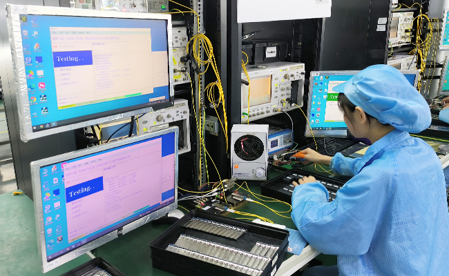
Optical transceiver TX RX performance test
Performance Testing

Each module is tested before shipment to help ensure stable optical and electrical performance.
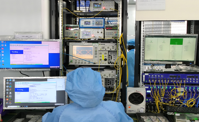
Optical transceiver compatibility test
Compatibility Verification

Compatibility validation is available for major switch and router platforms.
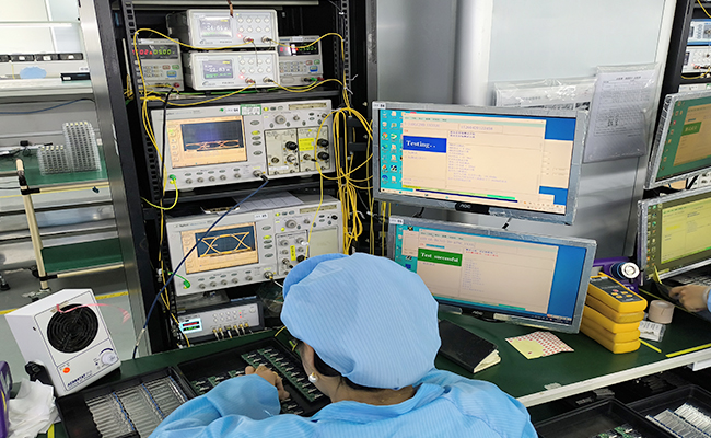
Optical transceiver aging and reliability test
Reliability Screening

Selected products support aging, temperature cycle, and stability testing for demanding applications.
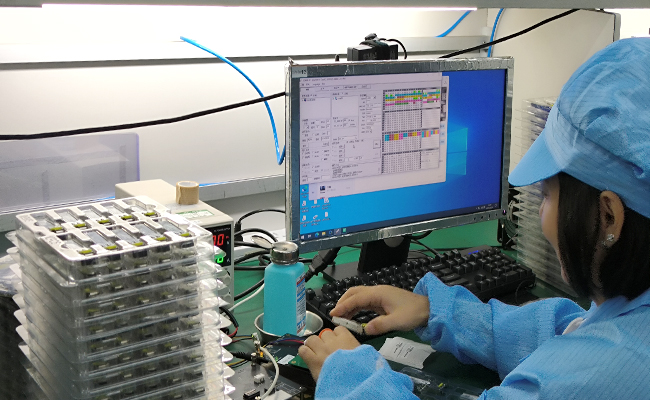
Automatic labeling and traceability for optical transceivers
Traceable Quality Control

Inspection and production records support more consistent quality control and batch traceability.

光模块产品详情订购信息---QSFP+